Posterior Composite Restorations Composites: Frequently Asked Questions (FAQ)

- Why do posterior composite restorations require replacement more often than silver amalgam restorations?
- How do I obtain posterior contacts consistently?
- How do I minimise the detrimental effects of polymerisation shrinkage of composites?
- What is the best way to perform the incremental build-up?
- Why do I sometimes get a white line at the cavity margin?
Why do posterior composite restorations require replacement more often than silver amalgam restorations?
Many patients choose to change their "ugly" silver amalgams for the esthetics of composite restorations. However, study after study show that many posterior composite restorations require replacement as soon as five years, which is about half the longevity of silver amalgam restorations. This should not necessarily be the case. A study of three selected private practices in Adelaide, Australia (Hawthorn & Smales 1997) has documented that posterior composite restorations can approach the longevity of silver amalgam restorations. It takes attention to detail.
Factors that contribute to premature replacement of composite restorations are:
- Secondary caries — either as a result of microleakage or open interproximal contacts causing food stagnation.
- Poor control of polymerisation shrinkage — the bugbear of composites.
- Excessive tooth wear or occlusal forces.
- Poor moisture control — results in a compromised tooth-composite bond and increased microleakage at their interface. Rubber dam isolation makes composite placement an enjoyable procedure!
- Inappropriate case selection.
How do I obtain posterior contacts consistently?
Traditionally, we use transparent plastic matrices for composites as this allows light transmission for curing. However, when used for shaping proximal restorations in posterior teeth, more often than not, tends to result in open contacts. Condensing to obtain a tight contact like we do with silver amalgam does not work as the plastic matrix band does not deform but springs back to its original position, and the mouldable composite resin cannot resist this action. Hence pre-wedging was advocated in an attempt to compensate-but that is a bit like a lottery!
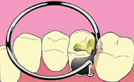
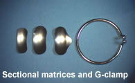
Using thin, dead soft sectional metal matrices which can be molded to shape and stay in the correct position will allow correct proximal contour and good proximal contacts consistently. Commercial systems using sectional matrices and G-clamps (figure left)are relatively expensive, but allow contacts to be achieved predictably. For eliminating all that aggravation over open contacts, the expense is worth it!
Matrices come in different widths and also with a scalloped edge (figure below). The G-clamp tine shape, the thickness of the bands and the wedging force the clamp applies vary between systems (table below).
| Brand | Thickness(mm) | Force(kg/mm²) |
|---|---|---|
| Keogh & Bertolotti (2001) Creating tight, anatomically correct interproximal contacts. Dent Clin North Am. 2001; 45:83-102. | ||
| Palodent | 0.04-0.05 | 0.55 |
| 3M/Garrison | 0.03 | 0.38 |
The 3M/Garrison Composi-tight G-clamp exerts a force sufficient to hold the band in place. The wedge needs to be inserted to also provide tooth separation. The newer Composi-tight Gold clamp exerts a higher separation force like the Palodent system. A wedge still needs to be inserted to adapt the band to the cervical portion of the cavity to prevent an overhang in the restoration.
Since the introduction of the abovementioned sectional matrix systems, many other brands have entered this market, introducing their own various variations on the theme.They all work well......unless the proximal box is too wide! This is where the different brands differentiate themselves, with some designs of the G-clamp remaining effective in wider cavities than others!
When the proximal box is too wide, and the area the G-clamp holds the sectional matrix in position is unsupported by tooth structure, the clamp will cause the sectional matrix to crumple! In such circumstances, I would build up that unsupported wall either free-hand or by using the sectional matrix held against the tooth by finger or an instrument, or even a regular amalgam maa until the G-clamp can be positioned securely.
After removing the sectional matrix band, light cure the proximal box again from both the buccal and lingual aspects to make sure it is properly light-cured.
Tip: If the proximal box has not cleared the contact, the thin, dead- soft sectional matrix band may not be able to pass through without first using a regular matrix band to create the space, or a wedge to open the contact.
How do I minimise the detrimental effects of polymerisation shrinkage of composites?
Composite resins have a polymerisation shrinkage of 3-7%. This shrinkage induces stress that is directed towards the middle of the polymerising composite resin mass (figure below), and polymerisation generally proceeds for about 24 hours! Along an unbonded, or free surface, this causes a contraction away from the surface, whilst along bonded surfaces, it induces stress of between 15-18 MPa (Davidson et al. 1984).

One of two things could happen at the tooth-composite interface when composite polymerises:
- Stress builds up when:
Bond strength > polymerisation shrinkage force. - Debonding occurs when:
Polymerisation shrinkage force > bond strength.
Debonding leads to microleakage, resulting in hypersensitivity and eventually secondary caries.
The ratio of bonded to unbonded surfaces, known as the cavity configuration factor ((C-factor) provides a relative scale of the expected stress induced by polymerisation shrinkage. For example, a class I cavity has a C-factor of 5 (5/1), a Class II mesio-occlusal cavity a C-factor of 4 (8/2) and the Class IV a very favourable C-factor of only 0.25 (1/4)!
Minimising Interfacial Stress
The key to successful composite restorations is minimising interfacial stresses. This can be achieved by:
- Development of maximum bond strength at the tooth-composite interface.
- Minimise polymerisation shrinkage stress on the tooth-composite interface by:
- Stress dissipation
- Elastic bonding concept
- Slow polymerisation
- Minimise composite resin bulk
- Incremental build-up of composite resin.
Maximum Bond Strength
A minimum bond strength of 25 MPa is generally considered to be desirable for clinical success of the composite restoration. The nature of the composite bond to enamel and dentine is different.
Enamel vs Dentine Bond Reliability
The composite-enamel bond is strong, predictable and reliable, and should exceed 25 MPa, whilst the composite-dentine bond is very variable depending on the site, depth and even the type of dentine, and may not always achieve a bond strength of 25 Mpa.
In general, the bond to carious or remineralised dentine is lower than normal dentine, except with moist bonding using polyalkenoic acid copolymer containing bonding agents (e.g. 3M Scotchbond Multipurpose and Single Bond) where it seems not to matter (Nakajima et al. 1999). Furthermore, both total and self-etch adhesives appear incapable of infiltrating the depth of the acid demineralised dentine (Suppa et al. 2005) resulting in a phenomena termed "nanoleakage".

Recent evidence also indicates that the hybrid layer, when exposed in the oral environment, may lasts for about 4 years only according to in vitro studies (Hashimoto et al. 2000). Apparently, dentinal enzymes cause degradation of the collagen leading to a breakdown of the collagen-hydrid layer interface (Pashley et al. 2004).
Enamel margins and the correct manipulation of bonding agents/adhesives can provide maximum bond strengths with good marginal adaptation.
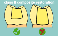
Tip: When the C-factor is high, like in Class II restorations, all margins must be in enamel —a dentine cervical margin in the proximal box is likely to debond!
Other factors for developing maximum bond strength are covered elsewhere:
- Equipment efficacy
- Polymerising light source
- Air-water syringe
- Bonding agent/adhesive. The "old-fashioned" three step of etch, prime and bond is still the most predictable, with the most convenient self-etching systems being the least reliable (see de Munck et al. 2005 for review).
- Bonding Technique
Stress Dissipation: Elastic Bonding Concept
The idea is to have a buffer layer that bonds to both the tooth and composite that is sufficiently elastic (represented by springs in the figure below) to absorb the stress that develops as the composite polymerises (figure below).
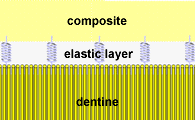
This elastic bonding is provided by:
- Resin modified glass-ionomer cement (RMGIC) lining or base
- Thick layer of bonding composite adhesive containing
- Flowable composite
Not all bonding agents provide a thick enough layer to function as an elastic bonding layer. As bonding agents/adhesives are generally unfilled, or lately, some are lightly filled with nano-sized fillers, this layer is the weakest link. Therefore, it is designed to be as thin as possible. However when extremely thin, the layer of bonding agent/adhesive does not allow for sufficient plastic deformation to absorb the polymerisation stresses.
Bonding agents that contain polyalkenolic acid copolymers. (E.g. 3M Scotchbond Multipurpose and Single Bond) apparently form a sufficiently thick layer to provide sufficient deformation to relieve some of the polymerisation stress.

Should you use a bonding agent that does not provide for enough stress relief, a layer of flowable composite can brushed onto the cavity preparation and light-cured over the adhesive, before placing the composite (rollover image left). As flowable composites are not heavily filled, they will be prone to wear, and should be confined to the internal cavity surfaces but brought to the edge only at the area most prone to debonding — the cervical margin of Class II and V cavities,especially if you you have to work with a dentine margin!
The benefit of flowable composite at the cervical margin is however controversial - some studies show it is beneficial but most others show it makes no difference or results in even more microleakage. While flowable adapts well to the cervical margin because of its lower viscosity, the lower filler loading implies its polymerisation shrinkage is much higher (up to approximately 12%) than normal restorative composites.
Stress Dissipation: Slow Polymerisation
The premise is that if polymerisation is slowed down, there will be time for the polymerisation shrinkage stress to dissipate. Studies have used different variations in intensity of the light-cure unit — almost all seem unsuccessful except the delayed cure system; take a five minute tea/coffee break between each increment for stress relief (for the composite — and you?). Only an academic could make a living taking that long to build up a restoration! Something practical next please!
Minimise Bulk of Composite Resin
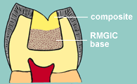
Use RMGIC (e.g. Fuji II LC, Photac Fill) as a dentine substitute in deeper cavities, so that less composite is required (figure left). This translates to less polymerisation shrinkage — it saves clinical time too!
Chemically-cured GIC (e.g. Fuji IX GP, Ketac Molar) can also be used, however, you have to wait for it to set. Furthermore, its bond to composite is not as good as RMGIC.
Incremental Build-Up
In small cavities, bulk packing can be performed, however, as they get larger, incremental build-up techniques become necessary because of:
- Limit of the depth of cure of polymerising lights to 2mm.
- Stress reduction at the tooth-composite interface. However, some authors argue that the different planes between increments actually increase the build-up of stress as measured by cusp-deflection (Versluis et al. 1996). Nevertheless, acknowledge that incremental build-up is necessary since light cure depth is limited.
Incremental build-up techniques are discussed below.
What is the best way to perform the incremental build-up?
There are many different techniques described, and it can get rather confusing.
A good way to visualize or work out from first principles regarding the best way to build each increment is to make each increment have as low a C-factor as possible.
Class I Composite Restorations
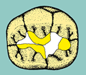
- Place base layer of composite (figure below). Light cure. I try to build it to the height of the central groove, so that the subsequent buccal and lingual cusp build-ups do not need to overlap and can be done at the same increment. Although the C-factor for this base layer is 5, it is thin (if necessary, line the cavity with RMGIC first so that the base layer does not have to be thick) and should there be debonding, the subsequent cuspal build-ups should seal the cavity. Studies support this since a horizontal layer yields the highest bond compared with other layering patterns (Nikolaenko et al. 2004).
- Restore alternate cusps. Each build-up should be separated from the other. Light cure.
- Restore remaining cusps. Light cure. This is a guide only, depending on the anatomy, extent of the cavity, depth etc. you may require one or two additional increments.



Quick Technique
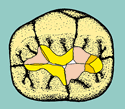
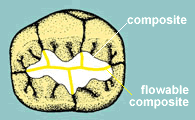
A quick way that sounds appealing is a simple two-step technique (figure left):
- Bulk pack then cut through the fissure pattern to produce separate increments of composite. Light cure.
- Flow flowable composite into grooves. Light cure.
For dentists who love stained grooves (but ask any patient-they are likely to prefer unstained grooves!), you could even under fill the flowable composite. Stain groove, then after light curing, add a transparent layer of flowable composite over the stain!
Unfortunately, the restoration starts to look tatty after a couple of years because of the poor wear characteristics of the flowable composite. Not a method I would recommend! I only mention it because some speakers on the circuit promulgate this technique and show beautiful pictures of the finished restoration at the time of completion.
Class II Composite Restorations
The incremental methods for restoring the proximal box include:
- Oblique layering
- Bucco-lingual layering
- Gingivo-occlusal layering
- Combination of the above
There does not seem to be a unanimous answer to which incremental technique provides the least stress — but any any incremental technique is better than bulk filling!
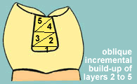
I prefer to build up the floor of the proximal box in one thin horizontal increment (C-factor 2) rather than one oblique (triangular) build-up (C-factor 1.5) because if the thin apex of the triangle is not properly bonded, the polymerisation shrinkage of the overlying bulk of the next increment may lift it off and make the gap worse (either way it's debonded!). My preference seems borne out by studies that indicate a horizontal layer results in a better bond than an oblique layer (Reis et al. 2004) After that, how I build up the rest of the proximal box depends on the width of the cavity!
Tip: The base of the proximal cavity can be quite a distance from the light source, therefore, to compensate for the fall-off in light reaching the initial composite layer, at least double or even triple the manufacturer's recommended light cure time for the composite you use.
Class II Narrow
Oblique build-up subsequent to the rectangular base layer is easier to perform when the proximal box is narrow (figure left). Each oblique increment will have a C-factor of 1.5.
Class II wide
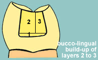
It is easier to use the buccal-lingual build-up technique where the proximal box is wide (figure left). Build the larger increment first as it has a small C-factor of 1. Leave a smaller bulk for the last increment which has a higher C-factor of 2.
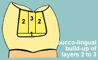
Where the box is wider, then both buccal and lingual wall increments (C-factor 1) can be built-up simultaneously, leaving a narrower mid-section (C-factor 2) last. However, if each of these rectangular increments is >2mm, then they will have to be built-up in smaller increments (rollover figure left).
Why do I sometimes get a white line at the cavity margin?
Polymerisation shrinkage of composite stresses the tooth-composite interface. The bond between composite and etched enamel is strong, and usually will not debond. However, if there is any structural defect or weakness in the nearby enamel, for example, if the enamel is too thin or there is a cleft in enamel, polymerisation shrinkage forces can cleave the enamel along and close to the cavity margin at this point of weakness (rollover figure left). This appears as a "white" line.
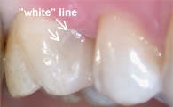
The "white" line can be repaired by using a small bur to remove it. Acid-etch the area then restore the defect with composite as usual. Merely acid-etching, placing adhesive followed by a flowable composite over the"white" line may not eliminate it as it could be covered over with a layer of excess set adhesive which is not bonded to the enamel that may not have been etched since it is beyond the cavity.
🔝

